Secure Boot
Secure Boot Evolution
A secure bootloader is a program that is first launched after minimal hardware initialization and ensures the security of the software that will run next. Most of the time, it checks authenticity with signatures and ensures confidentiality with encryption. The first known secure boot implementation is from the 1990s, by researchers William Arbaugh, David Farber, and Jonathan Smith, in the paper “A Secure and Reliable Bootstrap Architecture.” 1. They used a modified PC BIOS and cryptographic hashes stored in non-volatile memory to verify each step of the boot process. Shortly after, in the 2000s, console makers and smartphone manufacturers started adding secure boot to protect their firmware and prevent piracy. Secure boot adds security for the consumer by making sure that the hardware works as the vendor expected it to, but its main purpose is to allow manufacturers to protect their hardware, preventing users or attackers from bypassing intended restrictions. The widespread use of secure boot continued with Microsoft and the first implementation of UEFI (Unified Extensible Firmware Interface) in 2011, making the technology a PC standard. 2
Today, secure boot is implemented in most systems, and its use will continue to grow as European law enforces security requirements for all systems sold in the EU. This is done through the CRA (Cyber Resilience Act), which will take effect on 11 December 2027. As cyberattacks keep spreading and hardware can be an attack vector for sensitive information, the EU decided that vendors needed to integrate security solutions. The main ones are update support, key management guidelines, and trusted boot execution.
Root of Trust and Chain of Trust
A secure boot process is composed of a chain of trust where each step ensures security for the next one and extends trust as the boot chain continues. To start a chain of trust, we need a first step that we can trust, i.e. the root of trust. The root of trust is the first code to execute and the code we fully trust without any checks. It is usually a minimal, lightweight first-stage bootloader that handles the boot process of a secondary bootloader implementing more features. The root of trust depends on the hardware that we are working on. It can be firmware written by the hardware vendor, stored in ROM (read-only memory), and therefore impossible to tamper with. This is the case for the NXP RW61x architecture. It can also be a lightweight bootloader that lives in flash and locks itself through fuses or memory management modules to make itself immutable. The nRF architecture from Nordic uses this strategy by interacting with the hardware flash protection. 3
When the root of trust is implemented, the secondary bootloader, i.e. MCUBoot, takes the lead with more advanced features like recovery mode, update methods, multiple key management, and firmware verification. 4
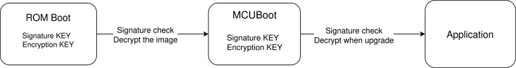 Figure 1: Chain of trust
Zephyr OS
Zephyr OS is a real-time operating system for embedded development and an open-source project under the Apache 2.0 license. A real-time operating system is an OS developed to manage timing constraints, ensuring predictability and stability. Zephyr’s philosophy is that the application logic and the hardware description are handled separately, allowing applications to be ported to different board infrastructures with minimal application logic modification. The same codebase is used but built for several boards by changing the target configuration. 5
How a project works
A Zephyr project starts with a manifest that lists every dependency needed. These can include dependencies outside the Zephyr implementation, vendor-specific board definitions, or application-specific components such as trusted firmware and secure boot implementations. It is also common to see a vendor create a fork of the Zephyr Git repository and add its custom board definition.
I worked a lot on the NXP fork of Zephyr to work on the RW612 target.
The Zephyr build tool is called west, and it manages everything about a project: project initialization, dependency updates, all available targets, build commands, flash commands, the debug interface, etc. It is the entry point for a Zephyr application. Starting with Zephyr is really simple: get a supported board from the thousands already integrated, compile a sample application like Hello World, and flash it. A simple project looks like this.
<app>
+-- CMakeLists.txt      # Build instruction for west
+-- app.overlay         # Custom hardware definitions
+-- prj.conf            # Kernel configurations
+-- VERSION
\-- src
    \-- main.c          # Source code
An advanced project layout can add sysbuild options. This allows us to build multiple applications at once, for example a bootloader and an application. It makes tracking configurations easier and keeps configurations local to the application instead of changing configuration directly in the bootloader implementation.
For this, a sysbuild folder can be added, containing a folder named after the application. Depending on which files are added and how they are named, configurations can be appended or overwritten.
<app>
+-- CMakeLists.txt          # Build instruction for west
+-- app.overlay             # Custom hardware definitions
+-- prj.conf                # Kernel configurations
+-- VERSION
+-- src/
|   \-- main.c              # Source code
\-- sysbuild/
    \-- mcuboot/
        +-- prj.conf        # Overwrite MCUBoot kernel configurations
        \-- mcuboot.conf    # Append MCUBoot kernel configuration
With that, when west is called with the option --sysbuild, MCUBoot will also be built with custom configurations.
Secure Boot with MCUboot Sample
Although getting a first application working can take less than an hour, mastering Zephyr takes a long time and can be frustrating when working on the upstream version of the project.
MCUBoot is the default bootloader used by Zephyr. In a Zephyr project, a specific version of MCUBoot can be specified, and the environment tool, west, pulls the correct version and manages updates. From the point of view of the Zephyr build tool, MCUBoot is like a normal application. It has the same folder structure and project configuration, and it is flashed using the same tool as an application built for the Zephyr kernel. The only difference is that MCUBoot does not rely on the Zephyr kernel and is a standalone application. The Zephyr project provides a wrapper around MCUBoot to integrate this solution with classic applications built for Zephyr.
MCUBoot manages images by reading a plaintext header/footer that contains several pieces of information about the image configuration (signature state, flags, hashes, size, etc.). MCUBoot adds many security features that a secure bootloader should have. All MCUBoot configuration is done by modifying the MCUBoot application Kconfig file.
Signature Verification
The most basic security feature to integrate with MCUBoot is signature verification. When compiling MCUBoot, the public part of a key pair is embedded with it. During signature verification, the bootloader verifies that an image was signed with a private key that corresponds to the embedded key hash.
But if MCUBoot can be tampered with, the hash of the public signature key embedded in MCUBoot could be replaced by an attacker. That is why it is possible to write secrets in specific parts of memory: OTP.
OTP memory stands for one-time programmable memory. It is used when data needs to be write-protected. It works by using fuses, and bit values can only pass from 1 to 0. This is the most common direction, but the opposite direction, from 0 to 1, is also possible. By using OTP, we can write the hash of the public key, and MCUBoot will read this value to verify the signature. Thanks to this, even if MCUBoot is tampered with by an attacker, signature verification relies on non-writable data. Writing to OTP depends heavily on the target architecture. It is often done directly with a debugger or in the board’s “manufacturer” or “recovery mode” with a custom API already implemented on the board.
With signatures implemented, authenticity is ensured.
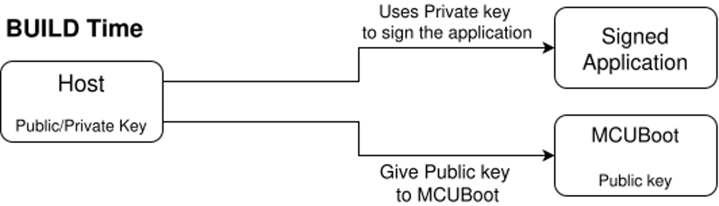 Figure 2: Signature verification with MCUBoot.
Signature verification is enabled with these Kconfig options.
MCUBoot kernel configurations:
CONFIG_BOOT_SIGNATURE_TYPE_ECDSA_P256=y
CONFIG_BOOT_SIGNATURE_KEY_FILE="sign.pem"
Application kernel configurations:
CONFIG_MCUBOOT_SIGNATURE_KEY_FILE="sign.pem"
The private key is specified for the application but is not embedded in the application, it is only used to sign the binary with the west tool from Zephyr. The public key is automatically derived from the private key when building MCUBoot and, depending on the project configuration, the hash of the full key is embedded in it. 6
For hardware key integration, the hash of the public key needs to be written into an OTP. MCUBoot then uses a hook, boot_retrieve_public_key_hash, to read that hash and only accepts images whose public key matches. The full public key still goes in the image header, but the bootloader never trusts an image until the key hash matches what is in OTP.
MCUBoot kernel configurations:
CONFIG_BOOT_HW_KEY=y
Application kernel configurations:
CONFIG_MCUBOOT_EXTRA_IMGTOOL_ARGS="--public-key-format full"
Because reading OTP depends on the hardware, it is the developer's responsibility to implement the hook function. I did it on an nRF5340 DK.
#define OTP_KEY_HASH_ADDRESS  0x00FF8100
#define SHA256_HASH_SIZE      32

int boot_retrieve_public_key_hash(uint8_t image_index,
                                  uint8_t *public_key_hash,
                                  size_t *key_hash_size)
{
    if (image_index > 1) {
        return -1;
    }

    if (*key_hash_size < SHA256_HASH_SIZE) {
        return -1;
    }

    uint8_t *otp_ptr = (uint8_t *)OTP_KEY_HASH_ADDRESS;
    memcpy(public_key_hash, otp_ptr, SHA256_HASH_SIZE);

    char hash_string[65];
    bin2hex(public_key_hash, SHA256_HASH_SIZE, hash_string, sizeof(hash_string));

    BOOT_LOG_DBG("OTP Hash: %s", hash_string);

    *key_hash_size = SHA256_HASH_SIZE;
    return 0;
}
Encrypted Images
Authenticity is not enough; confidentiality is also needed for a truly secure boot process. With encryption, images that are stored in external memory or are waiting to be updated can be stored as encrypted binaries. It also allows encrypted applications to be uploaded, with MCUBoot managing decryption when an update is requested. Encryption works like a signature, using a public-private key pair to encrypt a symmetric key. As with signature verification, this key must not be tampered with and must be non-writable. The difference is that MCUBoot has to use the private key from the key pair, so this key must not be readable. Managing private secrets on a board is more complicated, as processes such as MCUBoot need access to the secret without allowing an external user to read this data. Depending on the architecture, several secure memory components of the board must be used. For example, on an nRF5340 DK, the SPU (system protection unit) manages which process has read or write access to memory regions or peripherals such as a hardware accelerator. 7
Here is an example of how secrets can be leaked if MCUBoot is not read-protected and has embedded secrets. I built MCUBoot with a private key embedded in it that starts like this.
openssl pkey -in key/priv_custom_key.pem -outform DER -out key/priv_custom_key.der
xxd -b key/priv_custom_key.der | head -4
00000000: 00110000 10000010 00000100 10100101 00000010 00000001  0.....
00000006: 00000000 00000010 10000010 00000001 00000001 00000000  ......
0000000c: 10000001 11100001 10001101 11101010 01011010 01000111  ....ZG
00000012: 00111111 01110100 11110001 00100110 01110101 10110101  ?t.&u.
It is very easy to find a private encryption key because MCUBoot is open source and function hooks can be reverse engineered. When building MCUBoot, we have access to the .map files that map function calls to memory addresses. By looking at the MCUBoot source code, we can see that our private key is used in a function called autogen-enckey.c.
With a simple grep command, we can see the address associated with this file.
cat mcuboot/boot/zephyr/build/zephyr/zephyr.map | grep "autogen-enckey.c"
 .text          0x0000000000000000        0x0 app/libapp.a(autogen-enckey.c.obj)
 .data          0x0000000000000000        0x0 app/libapp.a(autogen-enckey.c.obj)
 .bss           0x0000000000000000        0x0 app/libapp.a(autogen-enckey.c.obj)
                0x000000000000ad58        0x4 app/libapp.a(autogen-enckey.c.obj)
                0x000000000000b6cf      0x4a9 app/libapp.a(autogen-enckey.c.obj)
 .comment       0x0000000000000020       0x21 app/libapp.a(autogen-enckey.c.obj)
                0x0000000000000568       0x18 app/libapp.a(autogen-enckey.c.obj)
 .debug_info    0x000000000004681f       0x70 app/libapp.a(autogen-enckey.c.obj)
 .debug_abbrev  0x0000000000003fde       0x47 app/libapp.a(autogen-enckey.c.obj)
 .debug_line    0x0000000000008e34       0x8a app/libapp.a(autogen-enckey.c.obj)
 .debug_str     0x0000000000003208       0x6a app/libapp.a(autogen-enckey.c.obj)
                0x00000000000005e8       0x36 app/libapp.a(autogen-enckey.c.obj)
The key is most likely at address 0xb6cf, because its size is 1193 bytes. We can compare the flash of MCUBoot with the key data and confirm that we have correctly located the private key inside the MCUBoot firmware at address 0xb6cf.
0000b6ca: 00000010 00000011 00000001 00000000 00000001 00110000  .....0
0000b6d0: 10000010 00000100 10100101 00000010 00000001 00000000  ......
0000b6d6: 00000010 10000010 00000001 00000001 00000000 10000001  ......
0000b6dc: 11100001 10001101 11101010 01011010 01000111 00111111  ...ZG?
0000b6e2: 01110100 11110001 00100110 01110101 10110101 01111001  t.&u.y
By looking at the ASCII representation of the data, we see that we successfully located the private key from the plain binary file of MCUBoot. We used the build's .map file to locate it, but we proved that it is possible to locate secrets in the binary.
Here is a schematic of how the encryption key is handled.
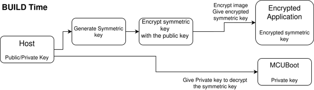 Figure 3: Encryption key handling in MCUBoot.
Application Update Workflow
MCUBoot implements a way to upgrade applications using two partitions: one for the running application and one for the pending future upgrade application. These future applications can be uploaded as encrypted binaries and decrypted on the fly by MCUBoot when the application is upgraded, as discussed in the previous section.
Partitions are defined alongside the kernel and sysbuild configurations in the source folder of the application.
Here is a simple example of a partition declaration file.
boot_partition: partition@0 {
label = "mcuboot";
reg = <0x00000000 0x10000>;
...
};
slot0_partition: partition@10000 {
reg = <0x00010000 0x70000>;
...
};
slot1_partition: partition@80000 {
reg = <0x00080000 0x70000>;
...
};
The first partition is for MCUBoot, with a size of 0x10000 bytes at address 0x0. The slot0_partition, i.e. the primary slot, is where the executed application lives in plaintext. The slot1_partition, i.e. the secondary slot, is where the uploaded encrypted application lives.
To understand how an update works, the client-server architecture first needs to be detailed. The default tool for uploading an application is called MCUmgr. When building the application, an SMP server is added to the application source code, and the host can use the MCUmgr client to communicate with this server.
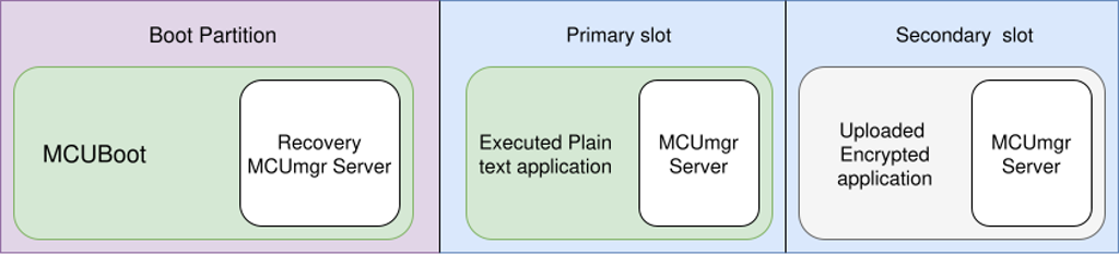 Figure 4: MCUmgr client-server architecture.
With MCUmgr added to the project, DFU is available. DFU (device firmware update) works by uploading an image using an MCU manager like MCUmgr and performing a swap. MCUmgr talks to the device over the Simple Management Protocol (SMP). When you upload a new firmware image, it is written to the secondary slot. The device keeps running from the primary slot until you decide to switch. The swap is the step where MCUBoot actually exchanges the contents of the two slots so that on the next reboot the new image runs from the primary slot. The previous image remains in the secondary slot so that if the new one fails to boot or is never confirmed, MCUBoot can automatically roll back to the known-good version on a subsequent reset.
Several transport layers are implemented in MCUmgr.
Serial: It uses a physical serial connection with the UART communication protocol and can be enabled with CONFIG_MCUMGR_TRANSPORT_UART=y.
BLE: You can push firmware updates to devices over Bluetooth Low Energy using MCUmgr. Because the link is wireless, security has to come from the transport itself: enable MCUMGR_TRANSPORT_BT_PERM_RW_AUTHEN=y so that read/write operations require an authenticated, encrypted connection, typically with bonding. That way only paired, trusted clients can perform updates. BLE can be enabled with CONFIG_BT_SMP=y.
IP: MCUmgr also supports DFU over IP networks using UDP and optional DTLS. A certificate can be passed with CONFIG_MCUMGR_TRANSPORT_UDP_DTLS=y. DFU over UDP can be enabled with CONFIG_MCUMGR_TRANSPORT_UDP=y.
The update method works by uploading an image to the secondary slot, listing the images, testing the image with its hash to set the secondary image to the pending state, resetting the board so MCUBoot performs the swap on the next boot, and then confirming the image with its hash if we want the update to be permanent and not reverted on the next reset.
mcumgr image list                                     # See firmware images
mcumgr image upload build/zephyr/zephyr.signed.bin    # Upload a new image
mcumgr image test <HASH>                              # Mark new image for test
mcumgr reset                                          # Reboot to initiate swap
mcumgr image confirm <HASH>                           # Confirm new image is working
Here is a schematic of how updates and security are handled. First, the board boots by following the blue path. If a new image is uploaded to the board, the green path is followed.
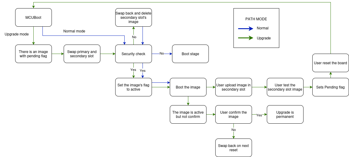 Figure 5: Upgrade workflow.
Swap Methods
The process by which MCUBoot exchanges images between the primary slot and the secondary slot is called a swap. Several swap methods exist. The original legacy method is the scratch method. It uses a specific partition to store and move sectors of the image. It works well but performs more reads and writes than newer methods, and it uses the scratch partition more than the other partitions, leading to uneven memory wear and possible inconsistencies if the partition is used for other purposes. To counter that, other similar methods exist, such as swap using offset. Swap using offset writes the image in the secondary slot with an offset of one sector. Once the swap starts, the first sector of the image in the primary slot is moved to the first sector of the secondary slot, which is empty thanks to the offset. It repeats the same procedure for every sector, leading to a new image in the primary slot and the old image starting at the beginning of the secondary slot without an offset.
Here is an example of how sectors behave when using scratch and offset.
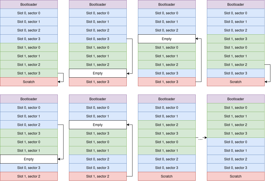 Figure 6: Swap using scratch.
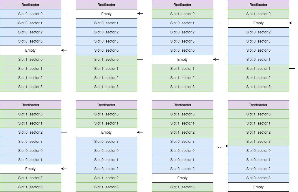 Figure 7: Swap using offset.
Swap using move also exists and works with the same principle as swap using offset, using the empty sector in the primary slot. 8
Kernel configuration for the MCUBoot application:
CONFIG_BOOT_SWAP_USING_SCRATCH=y?n
CONFIG_BOOT_SWAP_USING_OFFSET=y?n
CONFIG_BOOT_SWAP_USING_MOVE=y?n
Direct XIP
A completely different method can be used to execute a new version of firmware: Direct XIP (direct execution in place). With Direct XIP, MCUBoot does not swap slots at all. It simply chooses the image with the highest version and runs it in place from whichever slot it lives in. That avoids the time and wear of a swap, but it also means each image must be built to run at the address of its slot, as there is no position-independent code. Encrypted images cannot use Direct XIP, because decryption is done when moving into the primary slot. With Direct XIP, the CPU executes directly from the secondary slot, where the image remains unencrypted. 9
It can be configured with:
MCUBoot kernel configuration:
CONFIG_BOOT_DIRECT_XIP=y
Application configuration:
CONFIG_MCUBOOT_BOOTLOADER_MODE_DIRECT_XIP=y
To build for a specific address, an overlay can be passed to the west tool to specify particular configurations. For example, to build for the secondary slot according to the previously defined .dts file, an overlay called app_offset.overlay like this can be passed.
/ {
    chosen {
        zephyr,code-partition = &slot1_partition;
    };
};
And the app can be built with:
west build -d build -b <board> -- -DDTC_OVERLAY_FILE="app_offset.overlay"
Serial Recovery
If the firmware in the primary slot is broken or the normal SMP server never starts, you need a way to get a new image onto the device without relying on that firmware. Recovery mode does exactly that: a minimal SMP server is built into MCUboot itself. You enter it, for example, by holding a button at reset or sending a request in a certain time window. Once in recovery mode, you can use MCUmgr to upload an image directly into the primary slot, overwrite the broken firmware, and then update the application using the nominal path with the SMP server in the primary slot.
To enable MCUBoot serial recovery mode, these options must be enabled in the MCUBoot kernel configuration.
CONFIG_MCUBOOT_SERIAL=y
CONFIG_BOOT_SERIAL_ENTRANCE_GPIO=y
Here is an overview of alternative boot methods, Direct XIP and serial recovery.
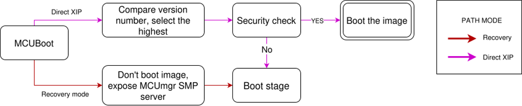 Figure 8: Alternative boot methods, Direct XIP and serial recovery.
Downgrade Prevention
To avoid an attacker replacing good firmware with an older, vulnerable version, you can enable downgrade prevention, often called anti-rollback in other bootloaders. MCUBoot then refuses to run an image from the secondary slot if its version is lower than the one currently in the primary slot. At boot, it will erase the secondary slot so the old image is no longer present. This is a software mechanism only; someone with a debugger could still flash an old image. For stronger guarantees against downgrades via debugger, you need a hardware security counter or similar mechanism.
Here is an example of a rejected image update.
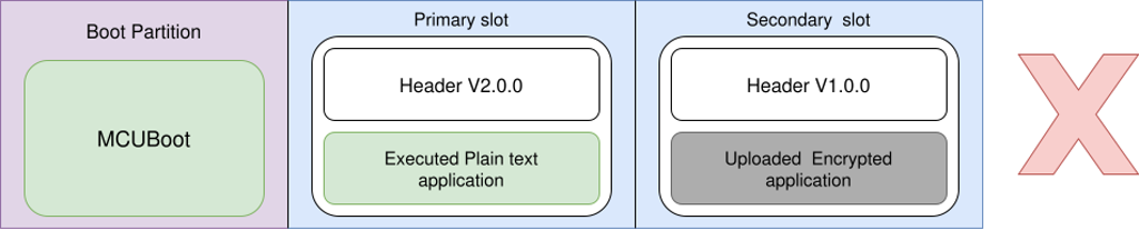 Figure 9: Rejected image update.
Hardware downgrade prevention prevents downgrades even if an application is directly flashed into the primary slot.
The nRF5340 DK uses one-time programmable memory, where each half-word can be written only once and cannot be erased. To implement a monotonic hardware counter for downgrade prevention, MCUboot splits the OTP into multiple slots, configured by CONFIG_MCUBOOT_HW_DOWNGRADE_PREVENTION_COUNTER_SLOTS.
Each slot represents one firmware update. The first update writes 1 to slot 0, the second update writes 2 to slot 1, etc. The current counter value is the maximum value found among all written slots. Once a slot is written, it cannot be changed or erased because it is in OTP. Writing to OTP can only increase the counter value, so older images will never be booted.
Each released image is built with a counter value CONFIG_MCUBOOT_HW_DOWNGRADE_PREVENTION_COUNTER_VALUE. On boot, MCUboot compares this value to the current counter in OTP. If the build value is greater than or equal to the OTP counter, the image is accepted and this value is written into the next available OTP slot. If the value is less than the current OTP counter, MCUboot rejects the image to prevent downgrades. The total number of updates is limited by the number of slots.
Here is a schematic of the OTP on an nRF5340 DK for hardware downgrade prevention, depending on different counter values.
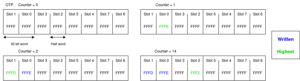 Figure 10: OTP counter values for hardware downgrade prevention.
The counter value is the highest value from all slots. Slots are written by decrementing them because OTP bits can only go from 1 to 0, so FFFF represents 0. On the nRF5340 DK, it is only possible to write full 32-bit words or half words, so slots are written as half words. Because bits can only transition from 1 to 0 and values are read in reverse, i.e. FFFF is 0 and not 65535, the counter value can only increase.
Here is an example of an accepted update.
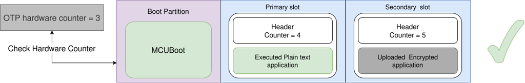 Figure 11: Accepted image update.